DIY Arduino Drone
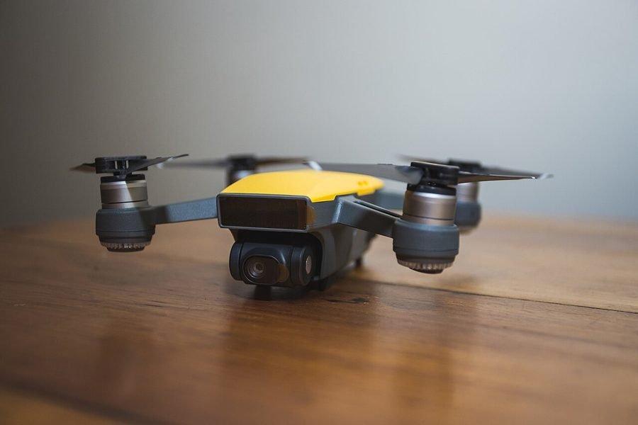
Image: Dji Spark (216743491).jpeg by Jp Valery via Wikimedia Commons, CC BY 3.0
Commercial flight controllers hide the actual stabilization logic behind a closed system; building one from an Arduino exposes exactly how a quadcopter reads its orientation and adjusts each motor to stay level and controlled.
This project uses an Arduino as the flight controller for a small quadcopter, reading gyroscope and accelerometer data (MPU6050) to sense tilt in real time and adjusting the speed of each of the four brushless motors, via their ESCs, to counteract drift and keep the craft stable in flight.
How It Works
- An MPU6050 IMU reports the drone's current tilt and rotation rate on all three axes, hundreds of times per second.
- A PID control loop compares the current orientation against the desired (usually level) orientation and computes correction values for each axis.
- Those corrections adjust the individual speed of each of the four motors through their ESCs — speeding up motors on the low side and slowing motors on the high side to level the craft.
- A separate RF/Bluetooth receiver relays pilot throttle and directional input, which the flight controller blends with the stabilization corrections.
Components
Arduino Uno/Nano/Pro Mini (flight controller)
MPU6050 gyroscope/accelerometer
4x brushless motors + ESCs
Quadcopter frame + propellers
RF/Bluetooth receiver for pilot input
LiPo battery
Applications
- Educational drone-building and flight-control demonstrations
- Foundational platform for aerial photography/videography extensions
- Teaching PID control theory in a physically visible system
Advantages
- Exposes the actual stabilization algorithm, unlike a closed commercial flight controller
- Strong hands-on demonstration of PID control theory
- Extendable toward GPS waypoint navigation or camera payload as a further project
Sample Code — PID Stabilization Outline
// Simplified PID stabilization outline - Arduino + MPU6050 #include#include MPU6050 mpu; float kP = 2.0, kI = 0.5, kD = 1.0; float errorSum = 0, lastError = 0; void loop() { float currentAngle = readTiltAngle(mpu); // from accelerometer/gyro fusion float targetAngle = 0; // level flight float error = targetAngle - currentAngle; errorSum += error; float derivative = error - lastError; float correction = kP * error + kI * errorSum + kD * derivative; lastError = error; adjustMotorSpeeds(correction); // apply to ESCs, opposite motors get opposite sign }
Related Research
Hours
Monday - Saturday: 9:00 AM - 5:00 PM
Sunday: Not Working
Location
2nd Floor, Comptron Arcade, Kallattumukku,
Thiruvananthapuram, Kerala 695012
Book Now
+91 9633118080