Wireless Load Control and Monitoring System
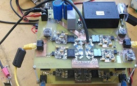
In industrial settings, loads are distributed across large areas. Running control wires is expensive. This project implements wireless load control using 433MHz RF communication. The transmitter unit has push buttons for selecting loads. The receiver decodes the signal and controls the relay. Voltage and current are monitored at the load side, and status is transmitted back to the transmitter for display.
Components
Arduino Uno (2 units)
433MHz RF Tx/Rx
ACS712 Current Sensor
4-Channel Relay Module
16x2 LCD
| Components | Hexkart | Flipkart |
|---|---|---|
| Arduino Uno | Buy Now | Buy Now |
| 433MHz RF Tx/Rx | Buy Now | Buy Now |
| ACS712 Current Sensor | Buy Now | Buy Now |
| 4-Channel Relay Module | Buy Now | Buy Now |
| 16x2 LCD | Buy Now | Buy Now |

433MHz RF Transmitter

The 433MHz RF transmitter module uses ASK (Amplitude Shift Keying) modulation to transmit digital data wirelessly. It operates at 433MHz ISM band and can achieve data rates up to 10kbps. The transmitter has a simple 4-pin interface (VCC, GND, DATA, ANT) and can be directly connected to Arduino digital pins. Data encoding is handled in software using libraries like VirtualWire or RadioHead for reliable communication.
433MHz RF Receiver
The 433MHz RF receiver module uses a super-regenerative circuit to demodulate ASK signals. It continuously listens on the 433MHz frequency and outputs the demodulated digital data. The receiver includes an automatic gain control (AGC) circuit to handle varying signal strengths. Combined with the transmitter, these low-cost modules enable bidirectional communication for load control commands and monitoring data.
4-Channel Relay Module
A 4-channel relay module provides independent control of four electrical loads. Each relay is rated for 250VAC at 10A, sufficient for controlling lighting, fans, and small motors. The module features optocoupler isolation between the Arduino control pins and the relay coils, ensuring protection for the microcontroller. In this project, each relay channel controls a separate electrical load based on wireless commands from the transmitter unit.
Circuit Diagram
Working Principle
This system has two units: a transmitter and a receiver, each controlled by an Arduino Uno. The transmitter unit has push buttons mapped to each load channel. When a button is pressed, the Arduino encodes the button ID and transmits it via the 433MHz RF transmitter module. The receiver unit's RF module captures the signal and the Arduino decodes it to determine which load channel to control. The corresponding relay is toggled (ON/OFF). For monitoring, the receiver unit also has an ACS712 current sensor measuring load current. This data is encoded and transmitted back to the transmitter unit via the same RF link. The transmitter displays the received current and voltage readings on a 16x2 LCD, providing real-time feedback on load status. The system supports bidirectional communication using a simple half-duplex protocol to avoid collisions.
Hours
Monday - Saturday: 9:00 AM - 5:00 PM
Sunday: Not Working
Location
2nd Floor, Comptron Arcade, Kallattumukku,
Thiruvananthapuram, Kerala 695012
Book Now
+91 9633118080