Traffic Light Simulator

Traffic Light Simulator Project Using Arduino
This educational project demonstrates how to build a working traffic light simulator using an Arduino UNO and LEDs. The system uses simple code to control the timing and sequence of red, yellow, and green lights, closely mimicking real-world traffic signals. This project is perfect for engineering students, electronics hobbyists, and anyone interested in learning about automation and embedded systems.
Project Overview:
The Arduino UNO board powers the LEDs and runs the traffic light logic. The code is uploaded to the board, and once powered, the LEDs cycle through the standard traffic light sequence automatically. This hands-on project helps users understand basic programming, circuit design, and the principles of traffic control systems.
Key Components:
- Arduino UNO
- Breadboard
- Jumper Wires
- LEDs (Red, Green, Yellow)
- 100 Ohm Resistors
Applications & Benefits:
- Ideal for school and college engineering projects
- Helps understand traffic control logic and automation
- Easy to build and customize for different scenarios
- Promotes hands-on learning in electronics and coding
For detailed circuit diagrams, code samples, or to get this project kit, contact Project Center Kerala.
| Components | Hexkart | Flipkart |
|---|---|---|
| Arduino | Buy Now | Buy Now |
| Bread Board | Buy Now | Buy Now |

Arduino

Arduino is an open source electronic prototyping platform.Arduino board designs use a variety of microprocessors and controllers. The boards are equipped with sets of digital and analog input/output (I/O) pins that may be interfaced to various expansion boards ('shields') or breadboards (for prototyping) and other circuits. The boards feature serial communications interfaces, including Universal Serial Bus (USB) on some models, which are also used for loading programs. The microcontrollers can be programmed using the C and C++ programming languages, using a standard API which is also known as the Arduino language, inspired by the Processing language and used with a modified version of the Processing IDE.
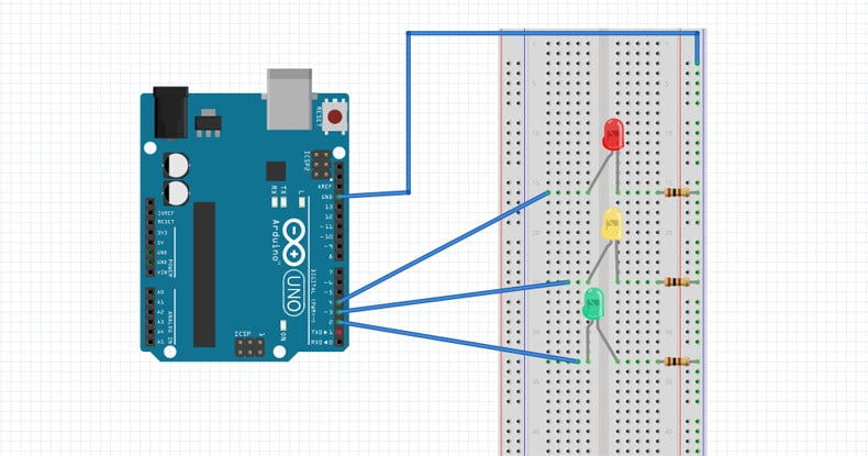
Circuit Diagram
Arduino Code
int GREEN = 2;
int YELLOW = 3;
int RED = 4;
int DELAY_GREEN = 5000;
int DELAY_YELLOW = 2000;
int DELAY_RED = 5000;
// basic functions
void setup()
{
pinMode(GREEN, OUTPUT);
pinMode(YELLOW, OUTPUT);
pinMode(RED, OUTPUT);
}
void loop()
{
green_light();
delay(DELAY_GREEN);
yellow_light();
delay(DELAY_YELLOW);
red_light();
delay(DELAY_RED);
}
void green_light()
{
digitalWrite(GREEN, HIGH);
digitalWrite(YELLOW, LOW);
digitalWrite(RED, LOW);
}
void yellow_light()
{
digitalWrite(GREEN, LOW);
digitalWrite(YELLOW, HIGH);
digitalWrite(RED, LOW);
}
void red_light()
{
digitalWrite(GREEN, LOW);
digitalWrite(YELLOW, LOW);
digitalWrite(RED, HIGH);
}
Hours
Monday - Saturday: 9:00 AM - 5:00 PM
Sunday: Not Working
Location
2nd Floor, Comptron Arcade, Kallattumukku,
Thiruvananthapuram, Kerala 695012
Book Now
+91 9633118080