Smart Grid Monitoring and Control System
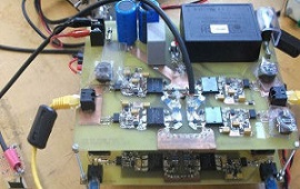
The traditional power grid is evolving into a smart grid with real-time monitoring and automation. This project demonstrates a smart grid monitoring system. ZMPT101B voltage sensors and ACS712 current sensors measure real-time voltage and current. The Arduino Mega calculates power consumption and transmits data via ESP8266 using MQTT. The dashboard displays live parameters with graphs. The system can control loads through relays based on demand-side management algorithms.
Components
Arduino Mega
ZMPT101B Voltage Sensor
ACS712 Current Sensor
ESP8266
4-Channel Relay Module
| Components | Hexkart | Flipkart |
|---|---|---|
| Arduino Mega | Buy Now | Buy Now |
| ZMPT101B Voltage Sensor | Buy Now | Buy Now |
| ACS712 Current Sensor | Buy Now | Buy Now |
| ESP8266 | Buy Now | Buy Now |
| 4-Channel Relay Module | Buy Now | Buy Now |

Arduino Mega

The Arduino Mega 2560 is the ideal controller for smart grid applications due to its abundant I/O pins (54 digital, 16 analog) and multiple hardware serial ports. It can simultaneously read multiple voltage and current sensors, control relay modules, and communicate with the ESP8266 WiFi module. Its 256KB flash memory accommodates complex monitoring algorithms and MQTT communication protocols.
MQTT Protocol over ESP8266
MQTT (Message Queuing Telemetry Transport) is a lightweight publish-subscribe messaging protocol ideal for IoT applications. The ESP8266 connects to an MQTT broker and publishes sensor data on specific topics. A dashboard application subscribes to these topics to display real-time data. The publish-subscribe pattern ensures efficient, low-bandwidth communication, making it perfect for smart grid monitoring where multiple parameters need constant updating.
4-Channel Relay Module
The 4-channel relay module provides independent control of up to four electrical loads. Each relay is rated for 250VAC 10A, suitable for controlling lights, fans, and other household appliances. The module includes optocoupler isolation between the Arduino control signals and the high-voltage relay contacts. In a smart grid scenario, these relays implement demand-side management by shedding non-critical loads during peak demand periods.
Circuit Diagram
Working Principle
The smart grid monitoring system continuously measures real-time electrical parameters at the consumer end. ZMPT101B voltage sensors and ACS712 current sensors feed analog readings to the Arduino Mega. The Arduino computes RMS voltage, RMS current, instantaneous power, energy consumption (kWh), and apparent power. This data is transmitted via the ESP8266 WiFi module to an MQTT broker. A cloud dashboard (Node-RED or custom web app) subscribes to the MQTT topics and displays live gauges, power trends, and historical energy usage. The system implements demand-side management: when total power consumption exceeds a configurable threshold, non-critical loads are automatically shed via the 4-channel relay module. Loads reconnect when consumption drops below the threshold. This demonstrates key smart grid concepts including real-time monitoring, two-way communication, and automated load control for grid stability.
Hours
Monday - Saturday: 9:00 AM - 5:00 PM
Sunday: Not Working
Location
2nd Floor, Comptron Arcade, Kallattumukku,
Thiruvananthapuram, Kerala 695012
Book Now
+91 9633118080