Power Factor Correction Using Microcontroller
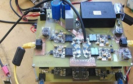
In industrial electrical systems, inductive loads like motors cause lagging power factor. A low PF results in higher electricity bills due to utility penalties. This project implements an Automatic Power Factor Correction system. Zero-crossing detectors measure the time delay between voltage and current zero-crossings to calculate the phase angle and PF. Based on the measured PF, the Arduino switches appropriate capacitor banks via relays.
Components
Arduino Uno
Zero Crossing Detector
Current Transformer
Capacitor Banks
Relay Module
| Components | Hexkart | Flipkart |
|---|---|---|
| Arduino Uno | Buy Now | Buy Now |
| Zero Crossing Detector | Buy Now | Buy Now |
| Current Transformer | Buy Now | Buy Now |
| Capacitor Banks | Buy Now | Buy Now |
| Relay Module | Buy Now | Buy Now |

Arduino Uno

Arduino Uno is a microcontroller board based on the ATmega328P. It has 14 digital input/output pins, 6 analog inputs, a 16 MHz quartz crystal, a USB connection, a power jack, an ICSP header and a reset button. It contains everything needed to support the microcontroller. In this project, the Arduino processes zero-crossing detection signals to calculate phase angle and power factor, then controls relay modules to switch capacitor banks accordingly.
Zero Crossing Detector
A zero crossing detector is a circuit that detects the point where the AC waveform crosses zero voltage. It outputs a pulse at each zero-crossing. By comparing the time difference between voltage and current zero-crossings, the phase angle between them can be determined. The power factor is the cosine of this phase angle. This is the fundamental measurement technique used in the APFC system.
Capacitor Banks
Capacitor banks are groups of capacitors connected in parallel or series to provide reactive power compensation. In an Automatic Power Factor Correction system, different capacitor values are switched into the circuit based on the required reactive power compensation. Capacitors provide leading reactive power to counteract the lagging reactive power drawn by inductive loads, thereby improving the overall power factor.
Circuit Diagram
Working Principle
This Automatic Power Factor Correction system operates by continuously monitoring the phase angle between voltage and current. Zero-crossing detectors generate pulses at each zero-crossing of both voltage and current waveforms. The Arduino measures the time delay between these pulses and calculates the phase angle. The power factor (cos φ) is computed from this angle. The system compares the measured PF with a target value (typically 0.95). If the PF is below target, the Arduino calculates the required capacitive reactive power and switches in the appropriate combination of capacitor banks via relays. Multiple banks of different capacitance values allow fine-grained correction. The system continuously adjusts as load conditions change, maintaining optimal power factor at all times.
Hours
Monday - Saturday: 9:00 AM - 5:00 PM
Sunday: Not Working
Location
2nd Floor, Comptron Arcade, Kallattumukku,
Thiruvananthapuram, Kerala 695012
Book Now
+91 9633118080