Over Voltage and Under Voltage Protection System
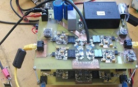
Voltage fluctuations are a common problem causing damage to sensitive equipment. This project implements an automatic over/under voltage protection system. The ZMPT101B sensor measures AC mains voltage. When voltage exceeds the upper threshold (e.g., 260V) or falls below the lower threshold (e.g., 180V), the Arduino de-energizes the relay, disconnecting the load. The LCD displays current voltage and protection status.
Components
Arduino Uno
ZMPT101B AC Voltage Sensor
Relay Module 5V
16x2 LCD
Buzzer
| Components | Hexkart | Flipkart |
|---|---|---|
| Arduino Uno | Buy Now | Buy Now |
| ZMPT101B Voltage Sensor | Buy Now | Buy Now |
| Relay Module 5V | Buy Now | Buy Now |
| 16x2 LCD | Buy Now | Buy Now |
| Buzzer | Buy Now | Buy Now |

Arduino Uno

Arduino Uno serves as the brain of the protection system, continuously reading voltage values from the ZMPT101B sensor through its analog input. It compares the measured voltage against user-configurable upper and lower threshold values. The Arduino implements a debounce mechanism and reconnection delay logic to prevent relay chattering during borderline voltage conditions.
ZMPT101B AC Voltage Sensor
The ZMPT101B is a high-precision voltage transformer module designed for AC voltage measurement. It uses a current-type voltage transformer with an onboard precision op-amp for signal conditioning. The module outputs an analog voltage proportional to the measured AC voltage, which can be read by the Arduino's ADC. It provides galvanic isolation between the high-voltage AC mains and the low-voltage control circuit, ensuring safety and noise immunity.
Relay Module
A 5V relay module acts as the electrically operated switch to connect or disconnect the load from mains supply. It uses an optocoupler for isolation between the Arduino control signal and the relay coil. When the Arduino detects voltage outside safe limits, it drives the relay coil LOW to de-energize the relay, opening the normally-open (NO) contacts and disconnecting the load. When voltage returns to normal and remains stable for the configured delay period, the relay is energized again.
Circuit Diagram
Working Principle
This system provides comprehensive protection against both over-voltage and under-voltage conditions. The ZMPT101B AC voltage sensor continuously samples the mains voltage and outputs an analog signal to the Arduino. The Arduino reads multiple samples, calculates the RMS voltage value, and compares it against the programmed threshold limits. If the voltage exceeds the upper threshold (programmable, typically 260V) or drops below the lower threshold (typically 180V), the Arduino immediately de-energizes the relay, disconnecting the protected load from mains. A buzzer sounds an audible alarm. The 16x2 LCD displays the current voltage reading and the system status (Normal/Over Voltage/Under Voltage). When the voltage returns to the safe range, the system waits for a configurable stabilization delay (typically 10-30 seconds) before reconnecting the load. This delay prevents nuisance tripping from brief voltage transients. The threshold values can be adjusted in the Arduino code or through push buttons in an advanced version.
Hours
Monday - Saturday: 9:00 AM - 5:00 PM
Sunday: Not Working
Location
2nd Floor, Comptron Arcade, Kallattumukku,
Thiruvananthapuram, Kerala 695012
Book Now
+91 9633118080