Line Follower Robot
Recently, many line following robots have been designed and utilized. Line follower robot is a self operating mobile machine that follows a line drawn on the floor. The path can be a visible black line on white surface or vice versa. Using ultrasonic sensors and IR array sensors which are set up inside the robot, the path location can be easily detected and followed. Line follower robot can be used in many industrial purposes. It can be used in carrying heavy and risky products. It can also transport radioactive material in a nuclear power plant. In restaurant, this robot can take orders and serve food accordingly.
Components
Arduino
IR Sensor
L298 Motor Driver
Smart Robot Car Tyres Wheels
DC Motor
Male to Female jumper Wires
On/Off Switch
Chasis
| Components | Hexkart | Flipkart |
|---|---|---|
| Arduino | Buy Now | Buy Now |
| L298 Motor Driver | Buy Now | Buy Now |
| IR Sensor | Buy Now | Buy Now |
| DC Motors | Buy Now | Buy Now |
| Wheels | Buy Now | Buy Now | Chasis | Buy Now | Buy Now |
| On/Off Switch | Buy Now | Buy Now |
Arduino

Arduino is an open source electronic prototyping platform.Arduino board designs use a variety of microprocessors and controllers. The boards are equipped with sets of digital and analog input/output (I/O) pins that may be interfaced to various expansion boards ('shields') or breadboards (for prototyping) and other circuits. The boards feature serial communications interfaces, including Universal Serial Bus (USB) on some models, which are also used for loading programs. The microcontrollers can be programmed using the C and C++ programming languages, using a standard API which is also known as the Arduino language, inspired by the Processing language and used with a modified version of the Processing IDE.
IR Sensor Modules
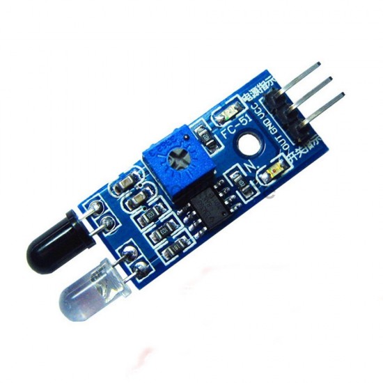
An infrared (IR) sensor is an electronic device that measures and detects infrared radiation in its surrounding environment. Infrared radiation was accidentally discovered by an astronomer named William Herchel in 1800. While measuring the temperature of each color of light (separated by a prism), he noticed that the temperature just beyond the red light was highest. IR is invisible to the human eye, as its wavelength is longer than that of visible light (though it is still on the same electromagnetic spectrum). Anything that emits heat (everything that has a temperature above around five degrees Kelvin) gives off infrared radiation.There are two types of infrared sensors: active and passive. Active infrared sensors both emit and detect infrared radiation. Active IR sensors have two parts: a light emitting diode (LED) and a receiver. When an object comes close to the sensor, the infrared light from the LED reflects off of the object and is detected by the receiver. Active IR sensors act as proximity sensors, and they are commonly used in obstacle detection systems (such as in robots)
L298 Motor Driver
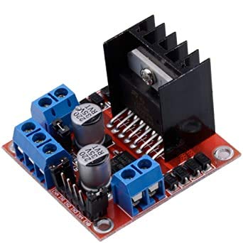
It is a high voltage, high current dual full-bridge driver designed to accept standard TTL logic levels and drive inductive loads such as relays, solenoids, DC and stepping motors. Two enable inputs are provided to enable or disable the device independently of the input signals. The emitters of the lower transistors of each bridge are connected together and the corresponding external terminal can be used for the con-nection of an external sensing resistor. An additional supply input is provided so that the logic works at a lower voltage.
They are mostly used when
- It is needed to operate different loads like motors and solenoid etc where an H-Bridge is required.
- High power motor driver is required.
- Control unit can only provide TTL outputs.
- Current control and PWM operable single-chip device are needed.
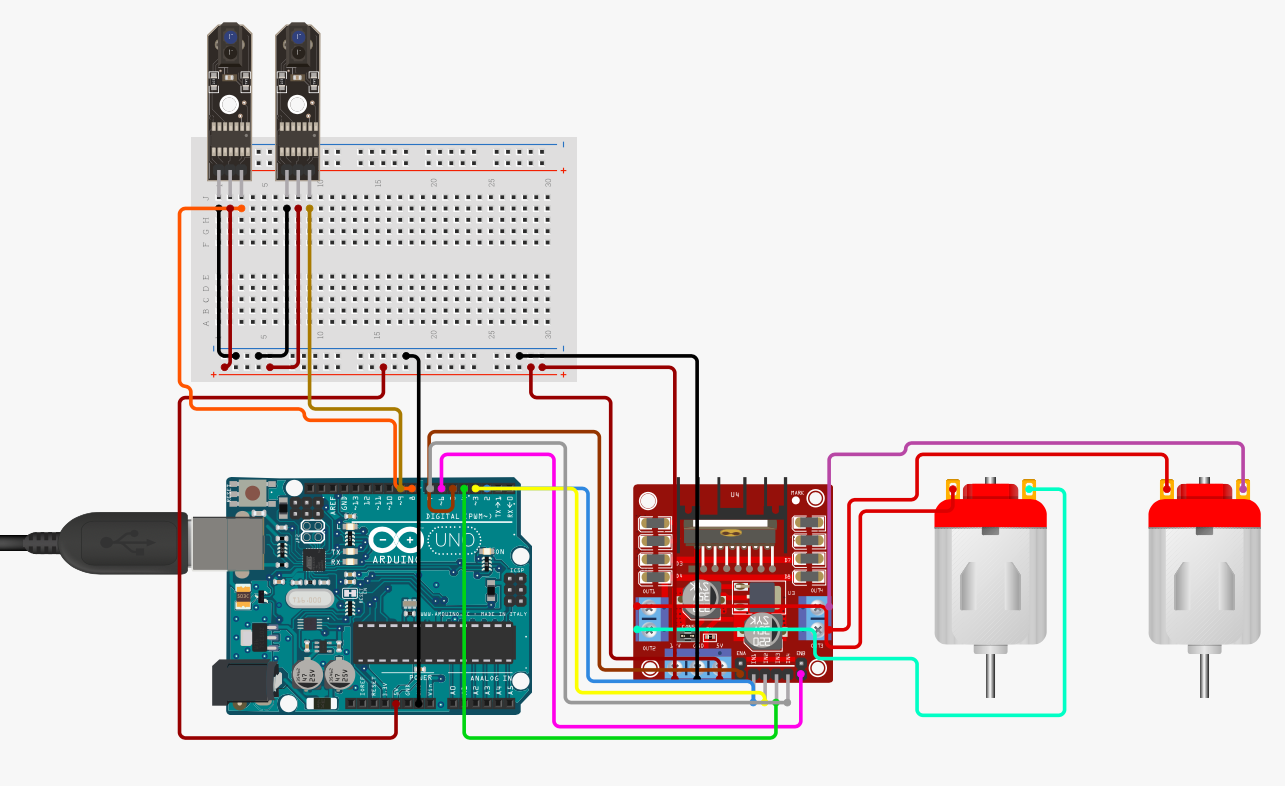
Circuit Diagram
Arduino Code
#define enA 10//Enable1 L298 Pin enA
#define in1 9 //Motor1 L298 Pin in1
#define in2 8 //Motor1 L298 Pin in1
#define in3 7 //Motor2 L298 Pin in1
#define in4 6 //Motor2 L298 Pin in1
#define enB 5 //Enable2 L298 Pin enB
#define R_S A0 //ir sensor Right
#define L_S A1 //ir sensor Left
void setup(){ // put your setup code here, to run once
pinMode(R_S, INPUT); // declare if sensor as input
pinMode(L_S, INPUT); // declare ir sensor as input
pinMode(enA, OUTPUT); // declare as output for L298 Pin enA
pinMode(in1, OUTPUT); // declare as output for L298 Pin in1
pinMode(in2, OUTPUT); // declare as output for L298 Pin in2
pinMode(in3, OUTPUT); // declare as output for L298 Pin in3
pinMode(in4, OUTPUT); // declare as output for L298 Pin in4
pinMode(enB, OUTPUT); // declare as output for L298 Pin enB
analogWrite(enA, 150); // Write The Duty Cycle 0 to 255 Enable Pin A for Motor1 Speed
analogWrite(enB, 150); // Write The Duty Cycle 0 to 255 Enable Pin B for Motor2 Speed
delay(1000);
}
void loop(){
if((digitalRead(R_S) == 0)&&(digitalRead(L_S) == 0)){forword();} //if Right Sensor and Left Sensor are at White color then it will call forword function
if((digitalRead(R_S) == 1)&&(digitalRead(L_S) == 0)){turnRight();} //if Right Sensor is Black and Left Sensor is White then it will call turn Right function
if((digitalRead(R_S) == 0)&&(digitalRead(L_S) == 1)){turnLeft();} //if Right Sensor is White and Left Sensor is Black then it will call turn Left function
if((digitalRead(R_S) == 1)&&(digitalRead(L_S) == 1)){Stop();} //if Right Sensor and Left Sensor are at Black color then it will call Stop function
}
void forword(){ //forword
digitalWrite(in1, HIGH); //Right Motor forword Pin
digitalWrite(in2, LOW); //Right Motor backword Pin
digitalWrite(in3, LOW); //Left Motor backword Pin
digitalWrite(in4, HIGH); //Left Motor forword Pin
}
void turnRight(){ //turnRight
digitalWrite(in1, LOW); //Right Motor forword Pin
digitalWrite(in2, HIGH); //Right Motor backword Pin
digitalWrite(in3, LOW); //Left Motor backword Pin
digitalWrite(in4, HIGH); //Left Motor forword Pin
}
void turnLeft(){ //turnLeft
digitalWrite(in1, HIGH); //Right Motor forword Pin
digitalWrite(in2, LOW); //Right Motor backword Pin
digitalWrite(in3, HIGH); //Left Motor backword Pin
digitalWrite(in4, LOW); //Left Motor forword Pin
}
void Stop(){ //stop
digitalWrite(in1, LOW); //Right Motor forword Pin
digitalWrite(in2, LOW); //Right Motor backword Pin
digitalWrite(in3, LOW); //Left Motor backword Pin
digitalWrite(in4, LOW); //Left Motor forword Pin
}
Hours
Monday - Saturday: 9:00 AM - 5:00 PM
Sunday: Not Working
Location
2nd Floor, Comptron Arcade, Kallattumukku,
Thiruvananthapuram, Kerala 695012
Book Now
+91 9633118080