Line Follower Robot
Control your music with a wave of your hand. This project builds a gesture-controlled Bluetooth speaker in which an Arduino reads hand motion through the MPU-6050 gyroscope and accelerometer module and translates it into playback commands — tilt forward to raise the volume, rotate to change tracks, flat palm to pause — sent wirelessly through the HC-05 Bluetooth module to the paired phone or speaker. Gesture-recognition logic filters raw accelerometer and gyroscope readings so six deliberate hand movements are distinguished from accidental motion, delivering responsive, contact-free audio control. Gesture interfaces like this are a fast-growing HCI research area and make an impressive, demo-ready BTech ECE project combining sensors, embedded programming and wireless communication.
Components
Arduino Uno
MPU-6050 Gyroscope & Accelerometer
HC-05 Bluetooth Module
PAM8403 Audio Amplifier Module
4 Ohm 3W Speaker
Male to Female jumper Wires
On/Off Switch
9V Battery Breadboard
5mm Acrylic Sheet 20cm x 12cm
| Components | Hexkart | Flipkart |
|---|---|---|
| Arduino | Buy Now | Buy Now |
| Bo motor (4) | Buy Now | Buy Now |
| 1003 | Buy Now | Buy Now |
| 1001 | Buy Now | Buy Now |
| 1002 | Buy Now | Buy Now |
| 1003 | Buy Now | Buy Now |
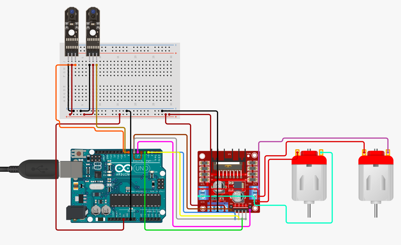
Circuit Diagram

Arduino Code
#define enA 10//Enable1 L298 Pin enA
#define in1 9 //Motor1 L298 Pin in1
#define in2 8 //Motor1 L298 Pin in1
#define in3 7 //Motor2 L298 Pin in1
#define in4 6 //Motor2 L298 Pin in1
#define enB 5 //Enable2 L298 Pin enB
#define R_S A0 //ir sensor Right
#define L_S A1 //ir sensor Left
void setup(){ // put your setup code here, to run once
pinMode(R_S, INPUT); // declare if sensor as input
pinMode(L_S, INPUT); // declare ir sensor as input
pinMode(enA, OUTPUT); // declare as output for L298 Pin enA
pinMode(in1, OUTPUT); // declare as output for L298 Pin in1
pinMode(in2, OUTPUT); // declare as output for L298 Pin in2
pinMode(in3, OUTPUT); // declare as output for L298 Pin in3
pinMode(in4, OUTPUT); // declare as output for L298 Pin in4
pinMode(enB, OUTPUT); // declare as output for L298 Pin enB
analogWrite(enA, 150); // Write The Duty Cycle 0 to 255 Enable Pin A for Motor1 Speed
analogWrite(enB, 150); // Write The Duty Cycle 0 to 255 Enable Pin B for Motor2 Speed
delay(1000);
}
void loop(){
if((digitalRead(R_S) == 0)&&(digitalRead(L_S) == 0)){forword();} //if Right Sensor and Left Sensor are at White color then it will call forword function
if((digitalRead(R_S) == 1)&&(digitalRead(L_S) == 0)){turnRight();} //if Right Sensor is Black and Left Sensor is White then it will call turn Right function
if((digitalRead(R_S) == 0)&&(digitalRead(L_S) == 1)){turnLeft();} //if Right Sensor is White and Left Sensor is Black then it will call turn Left function
if((digitalRead(R_S) == 1)&&(digitalRead(L_S) == 1)){Stop();} //if Right Sensor and Left Sensor are at Black color then it will call Stop function
}
void forword(){ //forword
digitalWrite(in1, HIGH); //Right Motor forword Pin
digitalWrite(in2, LOW); //Right Motor backword Pin
digitalWrite(in3, LOW); //Left Motor backword Pin
digitalWrite(in4, HIGH); //Left Motor forword Pin
}
void turnRight(){ //turnRight
digitalWrite(in1, LOW); //Right Motor forword Pin
digitalWrite(in2, HIGH); //Right Motor backword Pin
digitalWrite(in3, LOW); //Left Motor backword Pin
digitalWrite(in4, HIGH); //Left Motor forword Pin
}
void turnLeft(){ //turnLeft
digitalWrite(in1, HIGH); //Right Motor forword Pin
digitalWrite(in2, LOW); //Right Motor backword Pin
digitalWrite(in3, HIGH); //Left Motor backword Pin
digitalWrite(in4, LOW); //Left Motor forword Pin
}
void Stop(){ //stop
digitalWrite(in1, LOW); //Right Motor forword Pin
digitalWrite(in2, LOW); //Right Motor backword Pin
digitalWrite(in3, LOW); //Left Motor backword Pin
digitalWrite(in4, LOW); //Left Motor forword Pin
}
Hours
Monday - Saturday: 9:00 AM - 5:00 PM
Sunday: Not Working
Location
2nd Floor, Comptron Arcade, Kallattumukku,
Thiruvananthapuram, Kerala 695012
Book Now
+91 9633118080