Door Lock And Alert System Using Arduino

Nowadays, Security is one of the major concerns. People don't think about home security until they are burglarized. In order to deal with security concerns, we have implemented a smart electronic door lock system that uses RFID technology with password protection. It consists of a 4x4 keypad, RFID reader, 16x2 LCD, Arduino mega, and a 12v solenoid lock. Users can open the door using authenticated RFID card or by entering 6 digit password.The main motive is to design and implement a smart electronic door lock system. RFID door locks can be implemented in every environment where high security is required, from homes and shops to hospitals, schools, colleges, offices, etc. This system can be implemented wherever unauthenticated persons are prohibited.
Components
Arduino Uno
MFRC522 Rfid Reader
SIM900 GSM Module
LCD display 16*2
Resistos (220 Ohm )
SG90 Servo motor
4*4 keypad
Power supply
Buzzer
LED (Red,Green,Blue)
5V,2V Power adapter
| Components | Hexkart | Flipkart |
|---|---|---|
| Arduino Uno | Buy Now | Buy Now |
| Rfid Reader | Buy Now | Buy Now |
| LCD display 16*2 | Buy Now | Buy Now |
| SG90 Servo motor | Buy Now | Buy Now |
| 4*4 keypad | Buy Now | Buy Now |
| Buzzer | Buy Now | Buy Now |

Arduino

Arduino is an open source electronic prototyping platform.Arduino board designs use a variety of microprocessors and controllers. The boards are equipped with sets of digital and analog input/output (I/O) pins that may be interfaced to various expansion boards ('shields') or breadboards (for prototyping) and other circuits. The boards feature serial communications interfaces, including Universal Serial Bus (USB) on some models, which are also used for loading programs. The microcontrollers can be programmed using the C and C++ programming languages, using a standard API which is also known as the Arduino language, inspired by the Processing language and used with a modified version of the Processing IDE.
RC-522 Rfid Reader
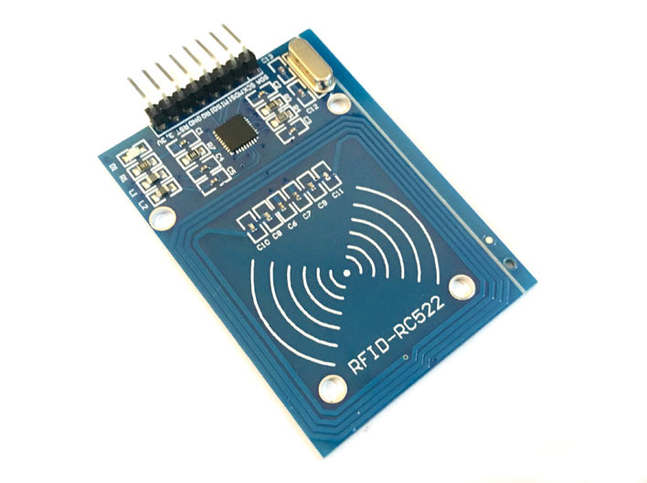
A radio frequency identification reader (RFID reader) is a device used to gather information from an RFID tag, which is used to track individual objects. Radio waves are used to transfer data from the tag to a reader.RFID is a technology similar in theory to bar codes. However, the RFID tag does not have to be scanned directly, nor does it require line-of-sight to a reader. The RFID tag it must be within the range of an RFID reader, which ranges from 3 to 300 feet, in order to be read. RFID technology allows several items to be quickly scanned and enables fast identification of a particular product, even when it is surrounded by several other items.
16*2 Lcd Display
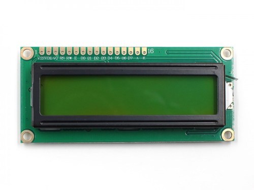
The term LCD stands for liquid crystal display. It is one kind of electronic display module used in an extensive range of applications like various circuits & devices like mobile phones, calculators, computers, TV sets, etc. These displays are mainly preferred for multi-segment light-emitting diodes and seven segments. The main benefits of using this module are inexpensive; simply programmable, animations, and there are no limitations for displaying custom characters, special and even animations, etc.
Servo Motor

Micro Servo Motor SG90 is a tiny and lightweight server motor with high output power. Servo can rotate approximately 180 degrees (90 in each direction), and works just like the standard kinds but smaller. You can use any servo code, hardware or library to control these servos. Good for beginners who want to make stuff move without building a motor controller with feedback & gear box, especially since it will fit in small places. It comes with a 3 horns (arms) and hardware.
SIM 900 GSM Module
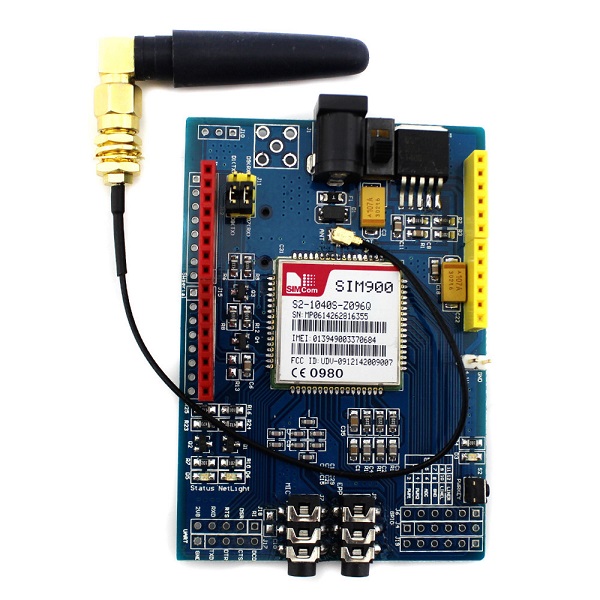
SIM900A Modem is built with Dual Band GSM based SIM900A modem from SIMCOM. It works on frequencies 900MHz. SIM900A can search these two bands automatically. The frequency bands can also be set by AT Commands. The baud rate is configurable from 1200-115200 through AT command. SIM900A is an ultra compact and wireless module. The Modem is coming interface, which allows you connect PC as well as microcontroller with RS232 Chip(MAX232). It is suitable for SMS, Voice as well as DATA transfer application in M2M interface. The onboard Regulated Power supply allows you to connect wide range unregulated power supply. Using this modem, you can make audio calls, SMS, Read SMS, attend the incoming calls and ect. through simple AT commands. This is a complete GSM module in a SMT type and made with a very powerful single-chip, allowing you to benefit from small dimensions. SIM 900A GSM Modem with serial and TTL outputs.
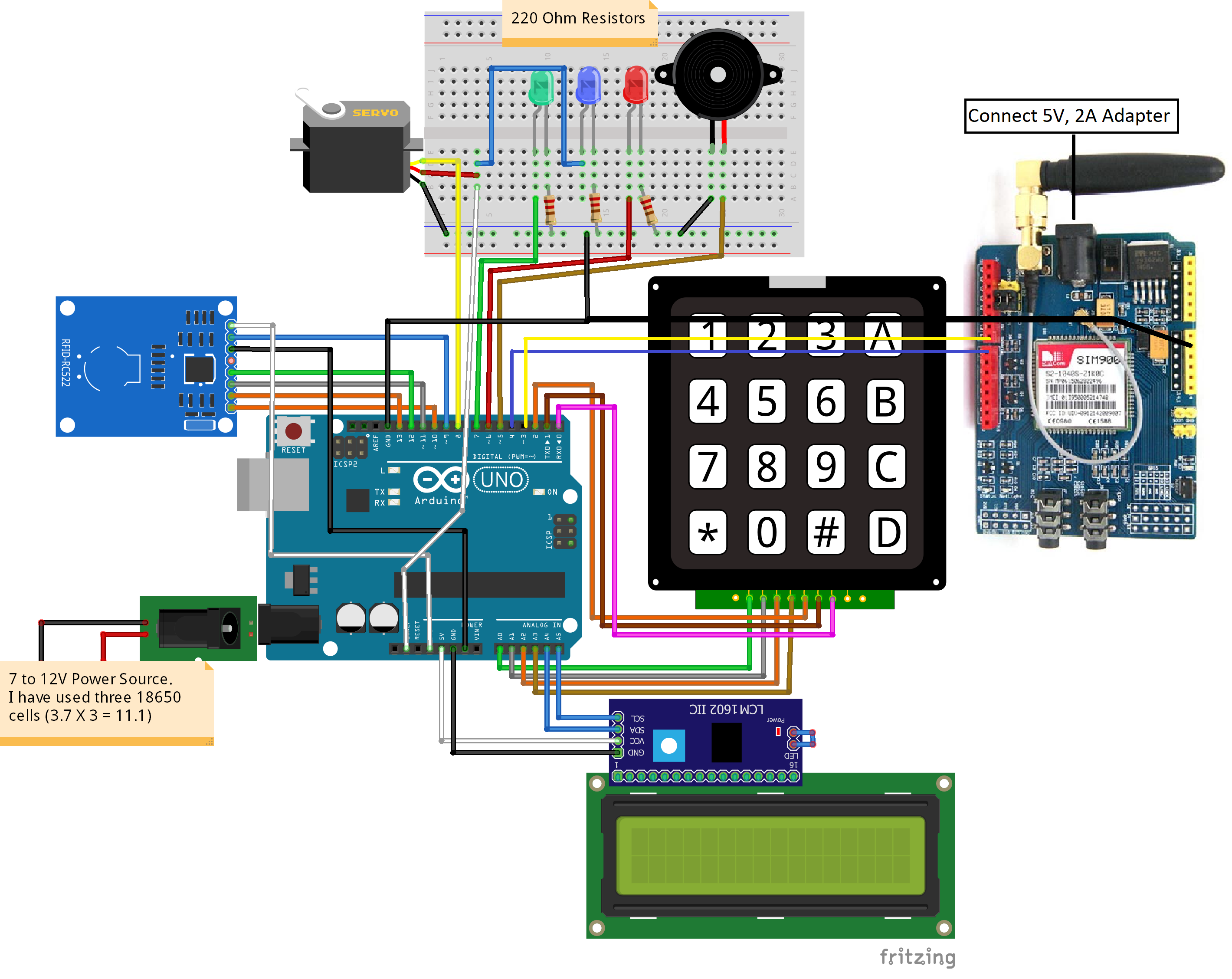
Circuit Diagram
Arduino Code
// Include required libraries
#include
#include
#include
#include
#include
#include
// Create instances
SoftwareSerial SIM900(3, 4); // SoftwareSerial SIM900(Rx, Tx)
MFRC522 mfrc522(10, 9); // MFRC522 mfrc522(SS_PIN, RST_PIN)
LiquidCrystal_I2C lcd(0x27, 16, 2);
Servo sg90;
// Initialize Pins for led's, servo and buzzer
// Blue LED is connected to 5V
constexpr uint8_t greenLed = 7
constexpr uint8_t redLed = 6;
constexpr uint8_t servoPin = 8;
constexpr uint8_t buzzerPin = 5;
char initial_password[4] = {'1', '2', '3', '4'}; // Variable to store initial password
String tagUID = "29 B9 ED 23"; // String to store UID of tag. Change it with your tag's UID
char password[4]; // Variable to store users password
boolean RFIDMode = true; // boolean to change modes
boolean NormalMode = true; // boolean to change modes
char key_pressed = 0; // Variable to store incoming keys
uint8_t i = 0; // Variable used for counter
// defining how many rows and columns our keypad have
const byte rows = 4;
const byte columns = 4;
// Keypad pin map
char hexaKeys[rows][columns] = {
{'1', '2', '3', 'A'},
{'4', '5', '6', 'B'},
{'7', '8', '9', 'C'},
{'*', '0', '#', 'D'}
};
// Initializing pins for keypad
byte row_pins[rows] = {A0, A1, A2, A3};
byte column_pins[columns] = {2, 1, 0};
// Create instance for keypad
Keypad keypad_key = Keypad( makeKeymap(hexaKeys), row_pins, column_pins, rows, columns);
void setup() {
// Arduino Pin configuration
pinMode(buzzerPin, OUTPUT);
pinMode(redLed, OUTPUT);
pinMode(greenLed, OUTPUT);
sg90.attach(servoPin); //Declare pin 8 for servo
sg90.write(0); // Set initial position at 0 degrees
lcd.begin(); // LCD screen
lcd.backlight();
SPI.begin(); // Init SPI bus
mfrc522.PCD_Init(); // Init MFRC522
// Arduino communicates with SIM900 GSM shield at a baud rate of 19200
// Make sure that corresponds to the baud rate of your module
SIM900.begin(19200);
// AT command to set SIM900 to SMS mode
SIM900.print("AT+CMGF=1\r");
delay(100);
// Set module to send SMS data to serial out upon receipt
SIM900.print("AT+CNMI=2,2,0,0,0\r");
delay(100);
lcd.clear(); // Clear LCD screen
}
void loop() {
if (NormalMode == false) {
// Function to receive message
receive_message();
}
else if (NormalMode == true) {
// System will first look for mode
if (RFIDMode == true) {
// Function to receive message
receive_message();
lcd.setCursor(0, 0);
lcd.print(" Door Lock");
lcd.setCursor(0, 1);
lcd.print(" Scan Your Tag ");
// Look for new cards
if ( ! mfrc522.PICC_IsNewCardPresent()) {
return;
}
// Select one of the cards
if ( ! mfrc522.PICC_ReadCardSerial()) {
return;
}
//Reading from the card
String tag = "";
for (byte j = 0; j < mfrc522.uid.size; j++)
{
tag.concat(String(mfrc522.uid.uidByte[j] < 0x10 ? " 0" : " "));
tag.concat(String(mfrc522.uid.uidByte[j], HEX));
}
tag.toUpperCase();
//Checking the card
if (tag.substring(1) == tagUID)
{
// If UID of tag is matched.
lcd.clear();
lcd.print("Tag Matched");
digitalWrite(greenLed, HIGH);
delay(3000);
digitalWrite(greenLed, LOW);
lcd.clear();
lcd.print("Enter Password:");
lcd.setCursor(0, 1);
RFIDMode = false; // Make RFID mode false
}
else
{
// If UID of tag is not matched.
lcd.clear();
lcd.setCursor(0, 0);
lcd.print("Wrong Tag Shown");
lcd.setCursor(0, 1);
lcd.print("Access Denied");
digitalWrite(buzzerPin, HIGH);
digitalWrite(redLed, HIGH);
send_message("Someone Tried with the wrong tag \nType 'close' to halt the system.");
delay(3000);
digitalWrite(buzzerPin, LOW);
digitalWrite(redLed, LOW);
lcd.clear();
}
}
// If RFID mode is false, it will look for keys from keypad
if (RFIDMode == false) {
key_pressed = keypad_key.getKey(); // Storing keys
if (key_pressed)
{
password[i++] = key_pressed; // Storing in password variable
lcd.print("*");
}
if (i == 4) // If 4 keys are completed
{
delay(200);
if (!(strncmp(password, initial_password, 4))) // If password is matched
{
lcd.clear();
lcd.print("Pass Accepted");
sg90.write(90); // Door Opened
digitalWrite(greenLed, HIGH);
send_message("Door Opened \nIf it was't you, type 'close' to halt the system.");
delay(3000);
digitalWrite(greenLed, LOW);
sg90.write(0); // Door Closed
lcd.clear();
i = 0;
RFIDMode = true; // Make RFID mode true
}
else // If password is not matched
{
lcd.clear();
lcd.print("Wrong Password");
digitalWrite(buzzerPin, HIGH);
digitalWrite(redLed, HIGH);
send_message("Someone Tried with the wrong Password \nType 'close' to halt the system.");
delay(3000);
digitalWrite(buzzerPin, LOW);
digitalWrite(redLed, LOW);
lcd.clear
i = 0;
RFIDMode = true; // Make RFID mode true
}
}
}
}
}
// Receiving the message
void receive_message()
{
char incoming_char = 0; //Variable to save incoming SMS characters
String incomingData; // for storing incoming serial data
if (SIM900.available() > 0)
{
incomingData = SIM900.readString(); // Get the incoming data.
delay(10);
}
// if received command is to open the door
if (incomingData.indexOf("open") >= 0)
{
sg90.write(90);
NormalMode = true;
send_message("Opened");
delay(10000);
sg90.write(0);
}
// if received command is to halt the system
if (incomingData.indexOf("close") >= 0)
{
NormalMode = false;
send_message("Closed");
}
incomingData = "";
}
// Function to send the message
void send_message(String message)
{
SIM900.println("AT+CMGF=1"); //Set the GSM Module in Text Mode
delay(100);
SIM900.println("AT+CMGS=\"+XXXXXXXXXXXX\""); // Replace it with your mobile number
delay(100);
SIM900.println(message); // The SMS text you want to send
delay(100);
SIM900.println((char)26); // ASCII code of CTRL+Z
delay(100);
SIM900.println();
delay(1000);
}
Hours
Monday - Saturday: 9:00 AM - 5:00 PM
Sunday: Not Working
Location
2nd Floor, Comptron Arcade, Kallattumukku,
Thiruvananthapuram, Kerala 695012
Book Now
+91 9633118080