Bluetooth Controlled Robot

This is a simple Micro-controller based car. The Micro-Controller is connected to the car. The Arduino is doing all this job. For receiving data wirelessly we are using the HC-05 Bluetooth module. At first, We have to connect/ pair the Bluetooth module with the phone (Android) you want to control. Now, we are doing different operations such as when we press the forward button then the Phone sends a data value to theBluetooth module. Next, we have to code in a way that if Arduino Gets a Certain Data (Suppose ‘F’ for forwarding) we have to make a certain condition for running the car in a certain direction. So, basically, there are many switch cases in the Arduino code. For a known condition or a switch case, the car will perform the added functions in the code. In the Same way, F, B, L, R are used for moving the car Forward, Backward, Left, Right movements.
Components
Arduino
Bluetooth module
L298 Motor driver
car Chasis
Li ion Battery
jumper wires
led
| Components | Hexkart | Flipkart |
|---|---|---|
| Arduino | Buy Now | Buy Now |
| Bluetooth Module | Buy Now | Buy Now |
| L298 Motor driver | Buy Now | Buy Now |
| Car chasis | Buy Now | Buy Now |

Arduino

Arduino is an open source electronic prototyping platform.Arduino board designs use a variety of microprocessors and controllers. The boards are equipped with sets of digital and analog input/output (I/O) pins that may be interfaced to various expansion boards ('shields') or breadboards (for prototyping) and other circuits. The boards feature serial communications interfaces, including Universal Serial Bus (USB) on some models, which are also used for loading programs. The microcontrollers can be programmed using the C and C++ programming languages, using a standard API which is also known as the Arduino language, inspired by the Processing language and used with a modified version of the Processing IDE.
Bluetooth Module
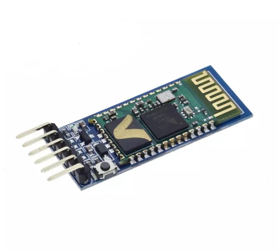
HC-05 is a Bluetooth module which is designed for wireless comunication. This module can be used in a master or slave configuration.It uses serial communication to communicate with devices. It communicates with microcontroller using serial port (USART).It is used for many applications like wireless headset, game controllers, wireless mouse, wireless keyboard and many more consumer applications.Bluetooth serial modules allow all serial enabled devices to communicate with each other using Bluetooth. It has 6 pins, 1. Key/EN: It is used to bring Bluetooth module in AT commands mode. If Key/EN pin is set to high, then this module will work in command mode. Otherwise by default it is in data mode. The default baud rate of HC-05 in command mode is 38400bps and 9600 in data mode. HC-05 module has two modes, 1. Data mode: Exchange of data between devices. 2. Command mode: It uses AT commands which are used to change setting of HC-05. To send these commands to module serial (USART) port is used. 2. VCC: Connect 5 V or 3.3 V to this Pin. 3. GND: Ground Pin of module. 4. TXD: Transmit Serial data (wirelessly received data by Bluetooth module transmitted out serially on TXD pin) 5. RXD: Receive data serially (received data will be transmitted wirelessly by Bluetooth module). 6. State: It tells whether module is connected or not.
L298 Motor Driver
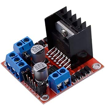
It is a high voltage, high current dual full-bridge driver designed to accept standard TTL logic levels and drive inductive loads such as relays, solenoids, DC and stepping motors. Two enable inputs are provided to enable or disable the device independently of the input signals. The emitters of the lower transistors of each bridge are connected together and the corresponding external terminal can be used for the con-nection of an external sensing resistor. An additional supply input is provided so that the logic works at a lower voltage.
They are mostly used when
- It is needed to operate different loads like motors and solenoid etc where an H-Bridge is required.
- High power motor driver is required.
- Control unit can only provide TTL outputs.
- Current control and PWM operable single-chip device are needed.
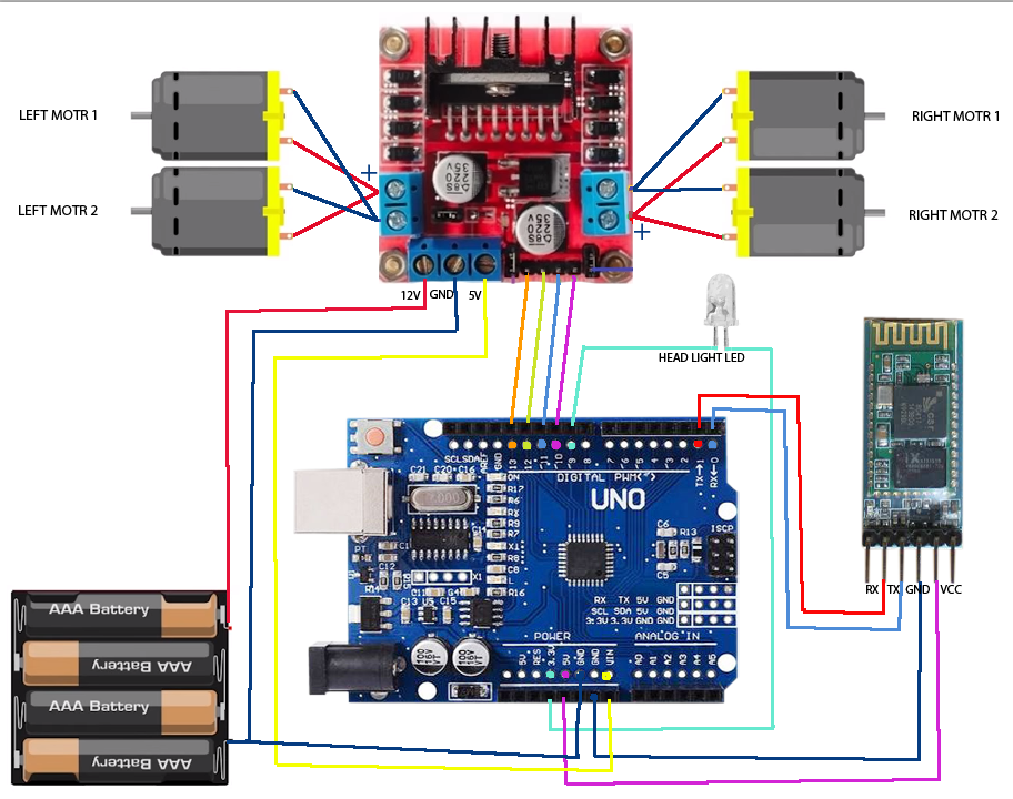
Circuit Diagram
Arduino Code
char t;
void setup() {
pinMode(13,OUTPUT); //left motors forward
pinMode(12,OUTPUT); //left motors reverse
pinMode(11,OUTPUT); //right motors forward
pinMode(10,OUTPUT); //right motors reverse
pinMode(9,OUTPUT); //Led
Serial.begin(9600);
}
void loop() {
if(Serial.available()){
t = Serial.read();
Serial.println(t);
}
if(t == 'F'){ //move forward(all motors rotate in forward direction)
digitalWrite(13,HIGH);
digitalWrite(11,HIGH);
}
else if(t == 'B'){ //move reverse (all motors rotate in reverse direction)
digitalWrite(12,HIGH);
digitalWrite(10,HIGH);
}
else if(t == 'L'){ //turn right (left side motors rotate in forward direction, right side motors doesn't rotate)
digitalWrite(11,HIGH);
}
else if(t == 'R'){ //turn left (right side motors rotate in forward direction, left side motors doesn't rotate)
digitalWrite(13,HIGH);
}
else if(t == 'W'){ //turn led on or off)
digitalWrite(9,HIGH);
}
else if(t == 'w'){
digitalWrite(9,LOW);
}
else if(t == 'S'){ //STOP (all motors stop)
digitalWrite(13,LOW);
digitalWrite(12,LOW);
digitalWrite(11,LOW);
digitalWrite(10,LOW);
}
delay(100);
}
Hours
Monday - Saturday: 9:00 AM - 5:00 PM
Sunday: Not Working
Location
2nd Floor, Comptron Arcade, Kallattumukku,
Thiruvananthapuram, Kerala 695012
Book Now
+91 9633118080